Process detail
Laser cutting & CNC bending
The two steps that decide most of the cost and accuracy of a sheet metal part. Here are the tolerances we design to and the rules behind them.
How a bend is defined
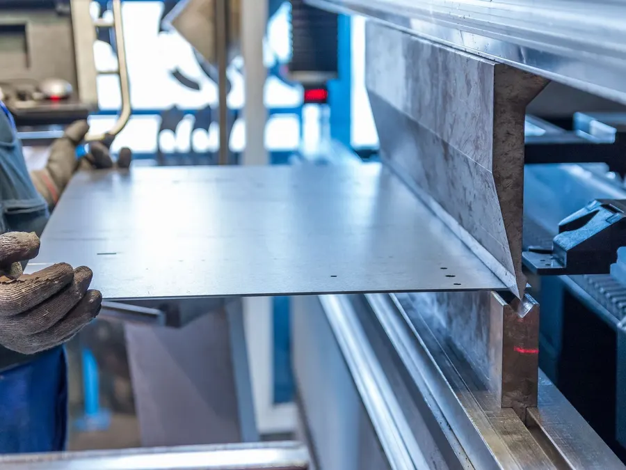
Bend accuracy depends on the V-die, material batch and grain direction. We calculate the flat pattern with our own bend tables (K-factor per material and tool), not with a generic value from CAD.
- Minimum flange length ≈ 4 × t (V-die of 6–8 × t).
- Inner radius ≈ 1 × t for steel, 1.5–2 × t for 6082 aluminium.
- Holes ≥ 2.5 × t + R from a bend line, or add bend relief.
Tolerances
Typical tolerances
Indicative values for this concept, in line with ISO 2768-m unless the drawing says otherwise. The drawing always governs.
| Feature | t ≤ 3 mm | 3 < t ≤ 10 mm | t > 10 mm |
|---|---|---|---|
| Contour, linear | ±0.10 mm | ±0.20 mm | ±0.30 mm |
| Hole position | ±0.10 mm | ±0.15 mm | ±0.25 mm |
| Minimum hole Ø (steel) | ≥ 1.0 × t | ≥ 1.0 × t | ≥ 1.2 × t |
| Minimum hole Ø (stainless) | ≥ 1.5 × t | ≥ 1.5 × t | on review |
| Edge taper | negligible | ≤ 0.1 mm | ≤ 0.3 mm |
| Feature | 1 bend | 2–3 bends | > 3 bends |
|---|---|---|---|
| Flange length | ±0.20 mm | ±0.30 mm | ±0.50 mm |
| Bend angle | ±0.5° | ±0.75° | ±1.0° |
| Hole to bend line | ±0.20 mm | ±0.30 mm | ±0.40 mm |
| Max bend length | 3000 mm | 3000 mm | 3000 mm |
| Feature | ≤ 400 mm | 400–1000 mm | > 1000 mm |
|---|---|---|---|
| Overall dimension | ±0.5 mm | ±1.0 mm | ±1.5 mm |
| Flatness of mounting face | 0.5 mm | 1.0 mm | 1.5 mm |
| Squareness | ±0.5° | ±0.5° | ±1.0° |
Need tighter values on a few features? Mark them on the drawing as functional. Tight tolerances on every feature mostly add inspection time, not function.